Lab 2 LED
อุปกรณ์
1.NodeMCU ESP-12E Development Board V2

2.สาย USB-A to Micro-B ตัวผู้ (ควรเป็นสายที่สามารถรับส่งข้อมูลได้)

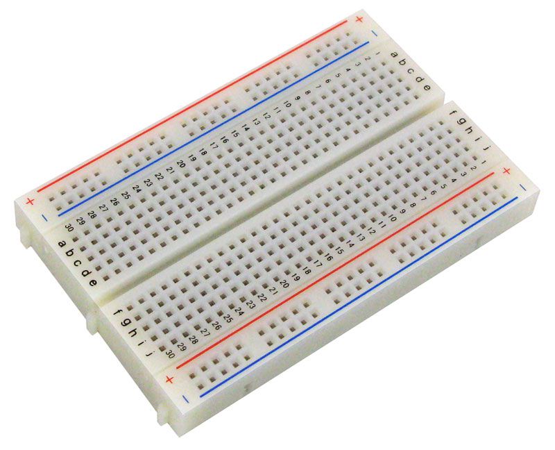
3.Breadboard
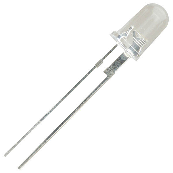
4.หลอด LED

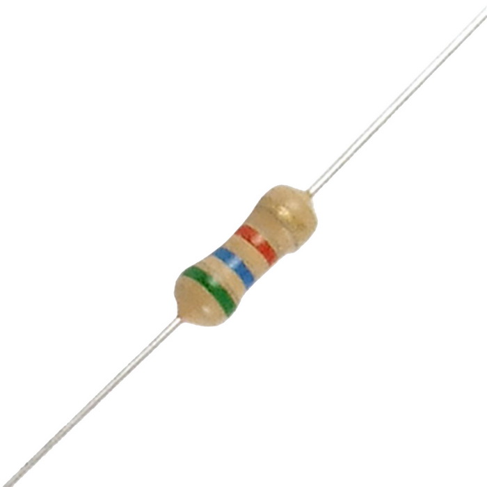
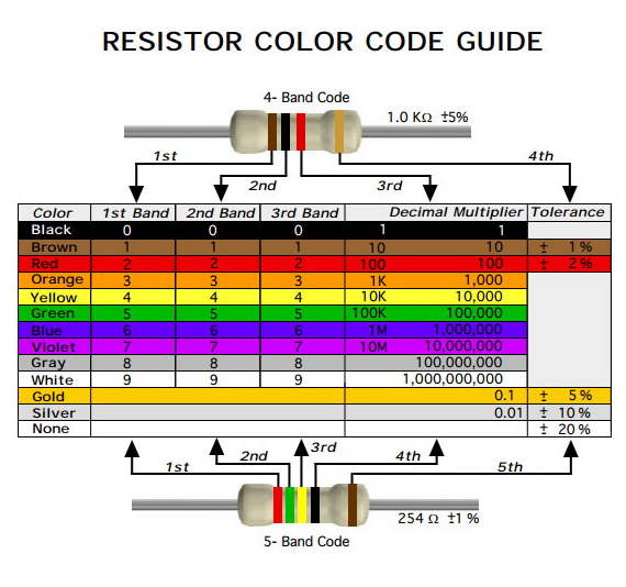
5.ตัวต้านทาน
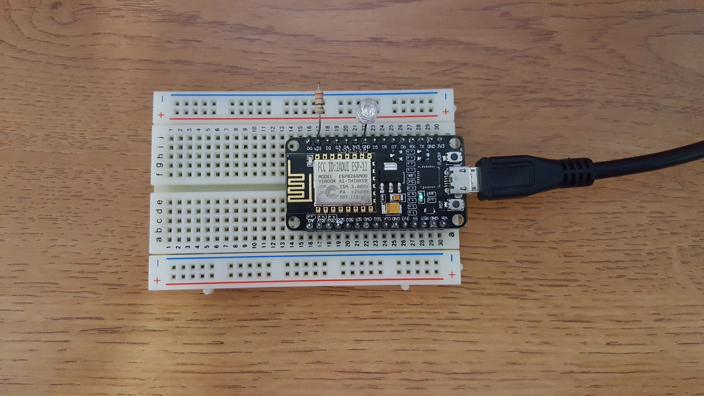
การต่อวงจร

ขั้นตอนการปฏิบัติ
1.เชื่อมต่อ NodeMCU ESP-12E Development Board V2 เข้ากับคอมพิวเตอร์ของท่านโดยการเสียบสาย USB-A to Micro-B ด้านที่เป็น Micro-B เข้ากับ NodeMCU ESP-12E Development Board V2 และเสียบด้านที่เป็น USB-A เข้ากับ Port USB ของคอมพิวเตอร์
2.เปิดโปรแกรม Arduino IDE ขึ้นมา จากนั้น ท่านจาสามรถพิมพ์หรือคัดลอก source code ข้างล่างไปวางในใน Arduino IDE
#define LED_PIN D1                      // GPIO5
void setup() {
  pinMode(LED_PIN, OUTPUT);             // Initialize the LED_BUILTIN pin as an output
}

// the loop function runs over and over again forever
void loop() {
  digitalWrite(LED_PIN, LOW);       // Turn the LED on (Note that LOW is the voltage level
                                    // but actually the LED is on; this is because
                                    // it is acive low on the ESP-01)
  delay(1000);                      // Wait for a second
  digitalWrite(LED_PIN, HIGH);      // Turn the LED off by making the voltage HIGH
  delay(2000);                      // Wait for two seconds (to demonstrate the active low LED)
}
3.จากนั้นให้ท่านทำการ verify และ upload source code ไปยัง NodeMCU ESP-12E Development Board V2
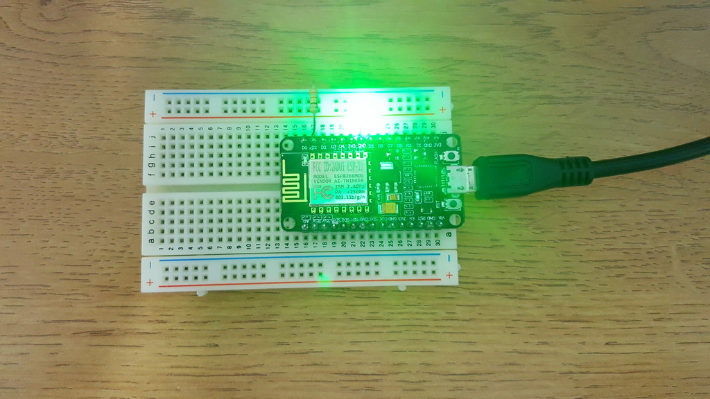
ผลลัพธ์
ท่านจะสังเกตเห็นว่าการกระพริบของ LED จะเปลี่ยนไป ซึ่งจะกระพิบเหมือนไฟบน NodeMCU ESP-12E Development Board V2 ใน Lab 1 เพราะว่าเราได้เปลี่ยนจากการกระพริบไฟบนบอร์ด เป็นการกำหนด Pin ที่ต่อกับ LED ซึ่ง Pin เรากำหนด คือ D1 หรือ GPIO5 ที่ได้ทำการต่อกับขา anode (+) ของ LED นั่นเอง ทั้งนี้ ท่านสารมารถลองเปลี่ยนเป็น Pin (GPIO) อื่น เพื่อทดสอบและทำความเข้าใจการทำงานของ Pin ได้ (ท่านสามารถดู Pinout ของ NodeMCU ESP-12E Development Board V2 ได้ที่เอกสาร ESP-12E Development Board)